How An Aeroplane Is Balanced. Part 4
Description
This section is from the book "The New Art Of Flying", by Waldemar Kaempffert. Also available from Amazon: The New Art of Flying.
How An Aeroplane Is Balanced. Part 4
Still another way of obtaining a certain amount of automatic stability is to employ vertical surfaces to prevent tilting and to distribute the pressure more evenly over the main surfaces. An example is to be found in the earlier Voisin machine, which is a biplane divided into cells by vertical curtains or partitions (Fig. 34). In practice, these partitions are found inadequate, for which reason the pilot of this Voisin type must right his machine by steering with the rudder. Thus, if the machine cants up on the left and down on the right, he steers to the left. This brings the right side up again because it is suddenly called upon to travel more quickly through the air than the left side, increased speed resulting in increased elevation. This Voisin type is one of the few constructions that does not fall within the scope of the Wright patent. Farman, who was one of the first pilots that ever tried a Voisin, abandoned it for the aileron machine, which bears his name. In the new Voisin machines (Fig. 35) no cells at all are to be found, but instead ailerons similar to those adopted by Farman. On the whole it must be confessed that the most successful machines at the present time are those in which the side-to-side balance is maintained either by warping the wings or by means of ailerons.
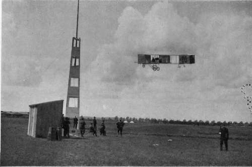
Fig. 34. Voisin machine of 1909. Machines such as this are no longer made.
Photograph by Edwin Levick.
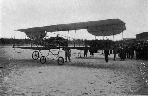
Fig. 35. The Voisin biplane of 1910. The old cellular construction is abandoned. Instead of vertical curtains between the main planes Farman ailerons are adopted.
Photograph by Edwin Levick.
Sometimes the vertical surfaces are distributed along the frame of the machine in the form of keels. Although they contribute a certain stability, it cannot be denied that they also increase the resistance and lower the speed. To prevent this so far as possible, and yet to retain whatever advantages they may have, it is customary to taper them. Examples of such tapering keels will be found on the Antoinette and Hanriot monoplanes (Fig. 36, Frontispiece). In a few years keels will probably disappear altogether. The advantages hardly offset the disadvantages. No special arrangement or design of keels has really ever succeeded in insuring automatic stability. Even now the best designers confine them to the extreme rear of the machine, where they act somewhat like a bird's tail.
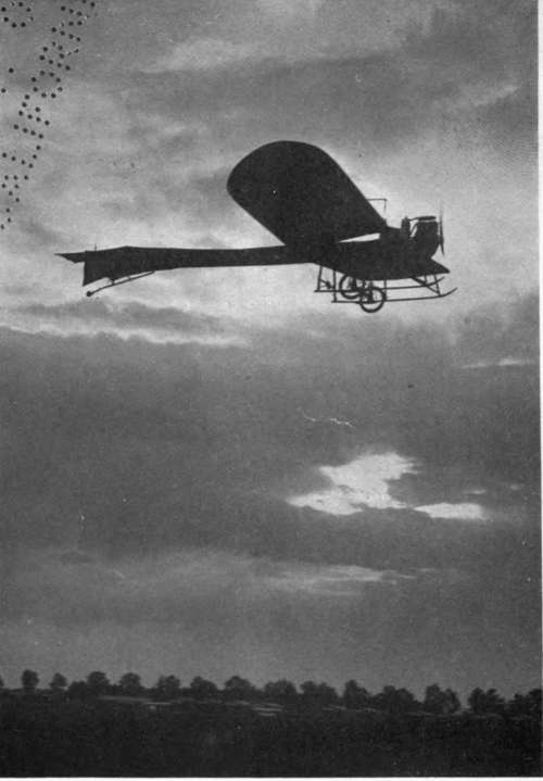
Fig. 36. The Hanriot monoplane in flight. The entire framework is covered with canvas to reduce resistance.
Mr. F. W. Lanchester, the distinguished English authority, has suggested that automatic stability can be insured by driving the aeroplane at speeds higher than those of the gusts, that are so liable to upset it. Just as the " Lusitania" at twenty-five knots dashes through waves and winds that would drive a fishing-smack to cover, so the high-speed aeroplane, in his opinion, would sail on, undeterred by the fiercest blast. Sixty miles an hour is the minimum speed that a machine should have, if his idea is correct. Moreover, he believes that, if the aeroplane is to have any extended use, it must travel very much faster than the motor-car.
Another means of attaining automatic stability consists in varying the angle of incidence by rocking the whole plane on a horizontal axis, which is done by Esnault-Pelterie.
The foregoing explanation of stability and stabilizing devices applies only to side-to-side balance. Fore-and-aft balance can be obtained, as in birds, by tails, such as are found in the Curtiss, Blériot, Antoinette, Santos-Dumont, Esnault-Pelterie, and indeed most machines.
The tail may be either a single horizontal surface or a cell, like a box kite. Almost every machine that now flies is provided with a tail to secure steadiness in flight. In the new Wright biplanes (Fig. 38) a single horizontal surface is used at the rear of the machine, a surface which also serves as an elevation rudder; for the Wrights have removed from the front of the machine those two parallel horizontal surfaces, which, in the early days of their work, were to them like the antennae of an insect, a means of feeling their way. The Wrights were the first who ever placed the rudder in front, and their example was quickly followed by Curtiss, Farman, Sommer, Voisin and other biplane makers. Whatever advantages this forward position of the horizontal rudder may have, it is certain that it increases the tendency of the machine to pitch in flight, because of the long lever-arm provided by the rods connecting the forward rudders with the main framework. When the Wrights reversed themselves and removed the horizontal rudder from the front and placed it at the rear, where it performed not only its old function, but also served as a tail (an instrument with which the earlier Wright machines were not provided), their example was promptly followed by Voisin (Fig. 35), Bréguet, Goupy, Caudron Frères and other constructors. It is safe to predict that in the future most biplanes will be provided with rear horizontal stabilising and elevating surfaces.
Fig. 35. The Voisin biplane of 1910. The old cellular construction is abandoned. Instead of vertical curtains between the main planes Farman ailerons are adopted.
Photograph by Edwin Levick.
From the very first, monoplanes have been provided with rear horizontal or elevation rudders, probably because such is the example offered by every bird and because the late Professor Langley adopted them after much experimenting. The Blériot, Antoinette and other monoplanes have rear horizontal rudders and also tails.
Continue to:
- prev: How An Aeroplane Is Balanced. Part 3
- Table of Contents
- next: How An Aeroplane Is Balanced. Part 5