Art. 69. Concrete-Steel Beams With Single Reinforcement
Description
This section is from the book "Cement And Concrete", by Louis Carlton Sabin. Also available from Amazon: Cement and Concrete.
Art. 69. Concrete-Steel Beams With Single Reinforcement
584. Definitions
In this discussion the word strain has its technical meaning, the relative change in length of a piece under stress. It is usually expressed as the ratio of the elongation (or shortening if in compression) to the original length of the piece. But for our purpose it is the ratio of the increment of change in length, occasioned by a given increment of stress, to the length of the piece before the increment of stress was applied. These two expressions for strain are usually considered equivalent, since, according to Hooke's law, the ratio between stresses and corresponding strains, for a given material, is constant within the elastic limit. But in dealing with concrete it is found that, even before the stresses become excessive, Hooke's law does not hold true. Bearing in mind, then, the meaning of the word strain, we represent as usual the ratio of stress to strain by E, the modulus of elasticity, or:
E = stress/strain.
Let E, = modulus of elasticity of steel.
Ee = modulus of elasticity of concrete in compression. fe = tension in steel, lbs. per sq. in. f = compression in concrete, lbs. per sq. in.
a = thickness of steel considered as a flat plate, or the area of imbedded steel bars per inch of width of beam z. y1 = distance the extreme fiber of concrete in compression is from the neutral axis.
y2 = distance the center of the steel reinforcement in the tension side of the beam is from the neutral axis. i = depth of concrete below reinforcement. d = y1 + y2 and h = d + i.
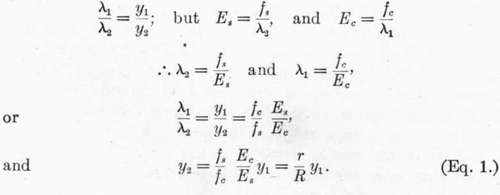
λ1 = unit compression of extreme fibers of concrete in compression. λ2 = unit elongation of steel in tension.
585. Formulas For Constant Modulus Of Elasticity
The cross-section of the beam, the graphical representations of the Strains and of the stresses are shown in the following diagrams:
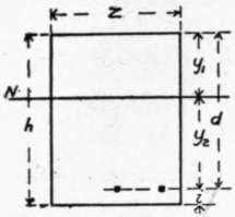
Fig. 10. CROSS-SECTION.
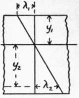
Fig. 11. STRAINS.
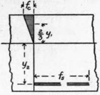
Fig. 12. STRESSES.
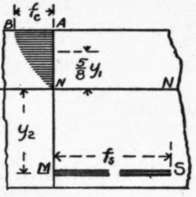
Fig. 13. STRESSES.
Figure 12 shows the conditions when the stresses are so small that the modulus of elasticity of the concrete may be considered constant, and this case will be first considered.
In the strain diagram, λ1 represents the deformation of the extreme fiber of concrete in the compression side of the beam, and the deformation of the steel. Since a section plane before bending is considered to be plane after bending, the steel is considered not to slip in the concrete, and NN is the neutral axis:
In the stress diagram the triangle NAB represents the total compressive stress on the concrete for unit width of beam, and is equivalent to a single force applied at the center of gravity of the triangle.
The total compressive stress for section of width z is 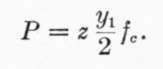 .
.
The total tension in the steel is T = zafs.
As we disregard the tensile strength of the concrete, and as the total normal compression and total normal tension on a section must be equal, as they are the two forces of a couple, we have 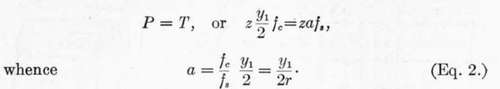 .
.
The point of application of the force P is = 2/3yx above the neutral axis, while the point of application of T is y2 below the neutral axis; the arm of the couple is therefore ((2/3)y1 + y2),and the moment of resistance is equal to either force into this arm,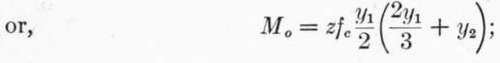 substituting the value of y2 given in (1) and reducing,
![]() .
.
586. Formulas For Varying Modulus Of Elasticity
The foregoing formulas are based on the supposition that the compressive stress in the extreme fiber of the concrete has not passed the point beyond which equal increments of stress no longer produce equal increments of strain or deformation. They are based, in other words, on the common theory of flexure, except so far as we have departed from the application of this theory in neglecting the tensile strength of the concrete. It is well known that even for steel and wooden beams this common theory does not, and is not meant to, apply outside the elastic limit. In the case of concrete, however, it has been found that, even for quite moderate stresses, the modulus of elasticity is not constant (Art. 56), but that after a certain stress is reached the modulus decreases with increasing stress. The effect of this upon the internal forces may be illustrated by the curve N B in Fig. 13. The extreme fiber is supposed to be subjected to the stress fc; the fibers nearer the neutral axis have a smaller stress per square inch, and the modulus of elasticity for this smaller stress is greater; but in order that a section that is plane before flexure shall be plane after flexure, the strain must be proportional to the distance from the neutral axis. It follows, then, that the stresses in the inner fibers do not decrease according to the ordinates of the triangle, but are greater than indicated by such ordinates. The exact form of the curve B N is not known, but the examination of a number of deformation curves has indicated that it is parabolic, and for the purpose of this discussion it may be considered a parabola with axis A B without serious error, although it is known the axis does not coincide with A B for stresses below the elastic limit of the concrete.
587. While the formulas derived in § 585 may represent, then, the conditions existing in a beam subjected to very moderate stresses, it appears that beyond the limit of stress at which the modulus of elasticity of concrete becomes variable, they should be so modified as to take into account this variable modulus.
Continue to:
- prev: Art. 68. The Strength Of Combinations Of Concrete And Steel
- Table of Contents
- next: Art. 69. Concrete-Steel Beams With Single Reinforcement. Part 2