Spherical Aberration And Coma
Description
This section is from the book "Airplane Photography", by Herbert E. Ives. Also available from Amazon: Airplane photography.
Spherical Aberration And Coma
Suppose we focus on a screen, by means of a simple convex lens the image of a distant point of light. Suppose for simplicity that this image is located on the axis of the lens and that light of only one color is used, such as yellow. It will be found that the smallest image that can be obtained is not a point, but a small disc. This is due to the fact that the rays of light passing through the outer portions of the lens are bent more than those passing through the lens in the region near the center. This effect is shown in Fig. 12 by the usual mode of representing it graphically. Here the figures 1, 2, 3, 4, represent distances from the axis of the lens, and the letters Ai, A2, A3, A4, the points of convergence of the rays from 1, 2, 3, 4, etc. These distances projected upward on to the produced lens points form a curve which shows at a glance the extent and direction of the error due to each part of the lens. This information is of value where the lens is fitted with an adjustable diafram. With some types of correction sharper definition may be obtained by reducing the aperture. With others, however, diaframing impairs definition, by destroying the balance between under and over correction which averages to make a good image. In aerial lenses it is not customary to use diaframs, as all the light possible is desired. Consequently the reduction of spherical aberration must be accomplished by proper choice of lens elements and their arrangement.
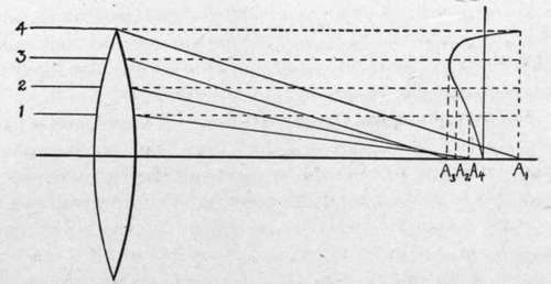
Fig. 12. - Diagrammatic representation of spherical aberration.
Off the axis of the lens the image of a point source takes on an irregular shape, due to oblique spherical aberration or coma.
Continue to:
Tags
camera, lens, airplane, aerial, film, exposure, photography, maps, birdseye