Parallel Motion Devices
Description
This section is from the book "Airplane Photography", by Herbert E. Ives. Also available from Amazon: Airplane photography.
Parallel Motion Devices
A form of suspension favored by the French consists of parallel bell cranks, rigidly linked together and held up by springs. Mountings of this sort are illustrated in Figs. 86, 87, 88 and 96. The guiding principle is that any sort of shock will be transformed into a straight up-and-down or side-wise motion of the camera, which is harmless. The mounting as adapted by the English surrounds the camera body, making the plane of support somewhere near the center of gravity. In certain of the French suspensions employing this principle the whole camera is hung below the bell cranks (Fig. 86), and then the Air Service appear to show that the chief virtue of the mounting lies in the approximation of the point of support to the center of gravity in the English cameras. A deRam camera supported by its cone, so that its center of gravity was considerably above the center of support gave rather poor results (Fig. 89a), but when the bell cranks were attached near the center of gravity, highly successful results were obtained (Fig. 896). The French deRam camera as ordered for the American Expeditionary Force was fitted with a bell crank supported in this position.
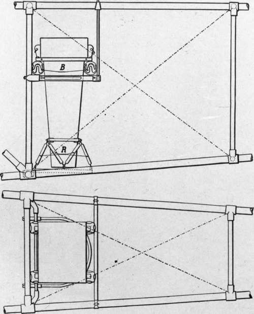
Fig. 85. - Tennis ball suspension, assisted by elastic bands attached to nose of camera, nose is restrained by heavy rubber bands. The net result is largely a matter of adjustment.
Tests on the English design made in the United States.
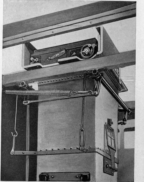
Fig. 86. - French spring and bell crank suspension.
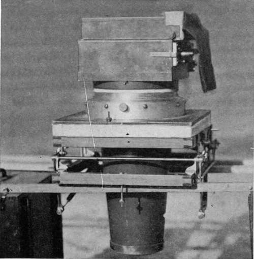
Fig. 87. - U. S. hand-operated 18x34 centimeter plate camera on bell crank mount with rotating turret.
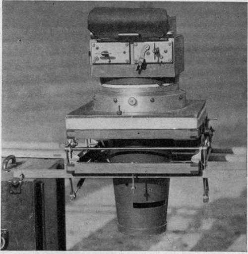
Fig. 88. - Same camera in plate changing position.
Figures 90 and 91 show a bell crank mounting furnished with a rotating turret. This was designed to facilitate the changing of magazines in the English B M camera, which is swung around through 90 degrees from the exposing position to bring the magazine near the observer. The camera shown in the mounting is the American hand-operated model (type M), in which there is the same necessity for turning in order to manipulate the bag magazine easily. The camera is shown in both exposing and plate changing positions. An important detail of these mounts is a safety catch, which must be fastened before the plane lands, in order to prevent the shocks of landing from producing oscillations sufficient to throw the camera out of the mount.
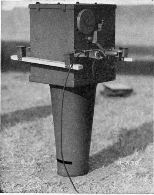
Fig. 90. - U. S. model deRam camera on anti-vibration mounting adjustable for the angle of incidence of the plane.
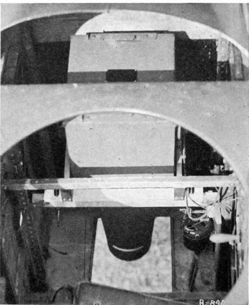
Fig. 91. - U. S. deRam camera and mount installed in photographic deHaviland 4 (Fig. 100). Viewed from above the observer's cockpit.
Continue to:
Tags
camera, lens, airplane, aerial, film, exposure, photography, maps, birdseye