III. The Suspension And Installation Of Airplane Cameras. Chapter XIV. Theory And Experimental Study Of Methods Of Camera Suspension. General Theory
Description
This section is from the book "Airplane Photography", by Herbert E. Ives. Also available from Amazon: Airplane photography.
III. The Suspension And Installation Of Airplane Cameras. Chapter XIV. Theory And Experimental Study Of Methods Of Camera Suspension. General Theory
In addition to the limitation of exposure set by the ground speed of the plane another limitation is set by the vibration of the camera. This may be caused either by the motor, or by the elastic reactions of the plane members to the strains of flight. Unlike the movement of the image due to the simple motion of the plane, movements due to vibration may be eliminated by proper anti-vibrational mounting of the camera.
The effect of vibration may show as an indistinctness of the whole imagethis is its only effect with a between-the-lens shutteror as a band or bands of indistinctness parallel to the curtain opening (Fig. 76). These are due to shocks or short period vibrations during the passage of the focal-plane shutter.
The obvious remedy for vibration troubles is to mount the camera on some elastic, heavily damping support, like sponge rubber or metal springs. Such a mounting should, however, be designed on sound principles derived from a proper analysis of the nature and effect of the possible motions of the camera. Otherwise, the vibrational disturbances may be increased rather than diminished by the camera mount. Such an analysis, based merely on general mechanical principles, shows that all motions of the camera are resolvable into six. These are three translational motions, namely, two at right angles in one plane such as the horizontal, and one in the plane at right angles to this (vertical); and three rotational motions, one about each of the above directions of translational motion as an axis (Fig. 77).
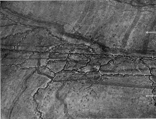
Fig. 76. - Captured German photograph, showing zones of poor definition due to vibration during passage of focal plane shutter aperture.
Brief consideration will show that only the latterthe rotational motionsare of any importance when the small displacements due to vibration are in question. To illustrate the negligible effect of vibrations which merely move the camera parallel to itself in any direction it is only necessary to imagine the camera moved parallel to the ground through a large distance, such as 10 centimeters. Now 10 centimeters motion of the camera at 3000 meters elevation means, with a 25 centimeter camera lens, 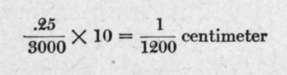 motion on the plate, which would be only a tenth the distance separable by a good lens. If we reduce this motion to the small fraction of a centimeter which vibration would actually produce, it is evident that such vibration is of absolutely no importance. Similarly, if we imagine the camera, under the same conditions, moved vertically with reference to the ground by ten centimeters, the scale of the picture would merely be changed by 1 210 0 or by yfoT centimeter on a 12 centimeter plate, again quite negligible.
When we consider motions of rotation, however, the case is quite different. If the camera is mounted so that the effect of any vibration is to rotate it around a horizontal axis, this is exactly equivalent to rotating the beam of light from the lens so that it sweeps across the plate. Thus a millimeter displacement of the lens of the camera with the plate remaining fixed gives approximately a millimeter motion of the image. Consequently, a rotation producing only a fraction of a millimeter's relative motion of lens and plate during the period the curtain aperture is over a given point would cause fatal blurringand the visible vibration of plane longerons and cross members is easily of half millimeter amplitude or more. Reduced to angular units it is easily shown that a rotation of one degree per secondwhich is quite slow as plane oscillations gois beyond the limits of toleration. Translational motions of large amplitude may be allowed, but the mounting of the camera must not permit these translations to be at all different for different parts of the camera.
The proper way to eliminate vibrational effects is to devise a mounting that will transmit only the translational shocks or that will transform the rotational ones into translations. Platforms pivoted and cross-linked so as to be free to move only parallel to themselves (described in the next chapter) represent one attempt to reach this result. Quite the simplest and most scientific form of mounting to achieve this end is to support the camera solely in the plane of the center of gravity. The principle here involved is easily grasped if we note that when we jar a camera supported above or below its center of gravity, the effect is to start the camera vibrating with the center of gravity oscillating pendulum-like about the point of support. The closer the center of gravity to the center of support, the smaller the moment of the body about the latter point.
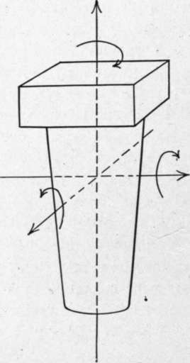
Fig. 77. - Diagram showing possible motions of the airplane camera: three of translation and three of rotation, and their combinations.
Continue to:
- prev: Devices For Recording Data On Plates
- Table of Contents
- next: Experimental Study Of Methods Of Camera Support
Tags
camera, lens, airplane, aerial, film, exposure, photography, maps, birdseye