The Curtiss Biplane
Description
This section is from the book "The New Art Of Flying", by Waldemar Kaempffert. Also available from Amazon: The New Art of Flying.
The Curtiss Biplane
Like the Wrights, Mr. Glenn H. Curtiss has departed somewhat from the type that he originally evolved. In his earlier machines (Fig. 25) the supporting planes consisted of " rubberized" silk stretched over the top of a light spruce frame. The spread of the planes was 26.42 feet, the depth 4.5 feet, the distance between the planes 5 feet, and the area 220 square feet. In the more recent machines the spread is 32 feet, the depth 5 feet, and the area 316 square feet.
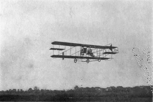
Fig. 25. Glenn H. Curtiss in one of his flying-machines, equipped with balancing-planes between the main planes.
Photograph by Edwin Levick.
The horizontal or elevation rudder of the Curtiss biplane consists of two parallel horizontal surfaces mounted in front of the machine and moved in unison by means of a steering-wheel. A long bamboo rod connects the horizontal rudder with the steering-wheel, the arrangement being such that by pushing or pulling the steering-wheel backward or forward, the rudder is respectively turned down or up.
The vertical rudder of the Curtiss machine is a single surface placed in the rear and also operated by the steering-wheel through the medium of cables. To work the vertical rudder the steering-wheel is rocked like the pilot-wheel of a steamboat. To secure steadiness in flight and to reduce the pitching effect a horizontal surface or tail is mounted in the rear.
Side to side balance was maintained in the Curtiss machine up to 1910 by means of two balancing planes of about 12 square feet in area, mounted between the two main planes. These balancing planes were swung in opposite directions by cables connected with a yoke partially surrounding the aviator's body and mounted to rock. By leaning from side to side the aviator moved the yoke and consequently the balancing-planes. The arrangement was such that the instinctive motion of the body swung the balancing-planes.
In the late Curtiss machines ailerons (Fig. 29) similar to those of the Farman biplane (q. v.) are employed. They are operated in the same manner as the old balancing-planes.
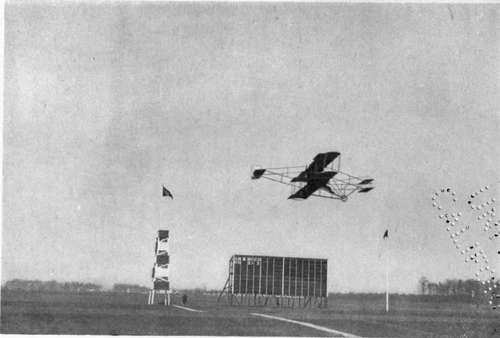
Fig. 29. One of the new Curtiss biplanes in flight. The machine is fitted with ailerons similar to those of the Farman machine pictured in Fig. 27.
Photograph by Edwin Levick.
The motors which drive the machine are made by Mr. Curtiss himself. On the larger machines the motors are of the well-known V-type and develop 50 horse-power. On the smaller machines 25 horse-power vertical cylinder motors are used. The engine is controlled by an accelerator pedal on the left of the steering column. There is also a throttle lever close to the pilot's seat. Another pedal under the action of the pilot's right foot is employed to cut off the ignition and to apply a brake to the front wheel of the chassis by which the machine is carried on the ground. Mr. Curtiss himself has driven machines with 100 horse-power motors.
The propellers are made of wood and are two-bladed. Their diameter is 6 feet, the pitch 5 feet, and the speed 1,200 revolutions a minute.
The machine starts and alights on three rubber-tired wheels.
For the Belmont Park aviation meeting of 1910 Mr. Curtiss made a machine which was practically a monoplane. The upper plane was reduced to a surface of almost negligible area. At the meeting in question the machine was not given a very extensive trial, so that it could not be compared with the Blériot and other machines that were entered.
Continue to: